搜索关键字:
SUMMARY
1.1Features
l Measurement is not affected by the variation of flow density, viscosity, temperature, pressure and conductivity. High accuracy measurement is guaranteed according to the linear measurement principle.
l No obstacle in the pipe, no pressure-loss and lower requirement for straight pipeline.
l DN 6 to DN2000 covers a wide range of pipe size. A variety of liners and electrodes are available to satisfy different flow characteristic.
l Programmable low frequency square wave field excitation, improving measurement stability and reducing power consumption.
l Implementing 16 bits MCU, providing high integration and accuracy; Full-digital processing, high noise resistance and reliable measurement; Flow measurement range up to 1500:1.
l High definition LCD display with backlight.
l RS485 or RS232 interface supports digital communication.
l Intelligent empty pipe detection and electrodes resistance measurement diagnosing empty pipe and electrodes contamination accurately.
l SMD component and surface mount technology (SMT) are implemented to improve the reliability.
1.2Main Applications
electromagnetic flowmeter can be used to measure the volume flow of conductive fluid in a closed pipeline. It is widely applied in the flow measurement and control in the fields of chemical and petroleum industry, metallurgy industry, water and waste water, agriculture and irrigation, paper making, food and beverage industry and pharmaceutical industry.
1.3Ambient Conditions
Ambient temperature: sensor: -25℃ to + 60℃; converter: -25℃ to + 60℃.
Relative humidity: 5% to 90%;
1.4Working Conditions
Maximum fluid temperature:
Compact type: 60℃
Remote type: Teflon 150℃
Neoprene 80℃; 120℃
Polyurethane 70℃
Fluid conductivity: ≥ 5mS/cm
1. WORKING PRINCIPLES
2.1 Measuring Principles
The measuring principle of electromagnetic flowmeter is based on the electromagnetic induction law of Farady. The sensor is mainly composed of measuring tube with isolate lining, a pair of electrodes installed by penetration of the measuring tube wall, a pair of coils and iron core to produce working magnetic field. When the conductive fluid flows through the measuring tube of the sensor, the voltage signal in direct proportion to the average flow velocity of the fluid will be inducted on the electrodes. The signal is amplified and treated by the transmitter to realize various display functions.

2.2 Converter Circuit Schematic
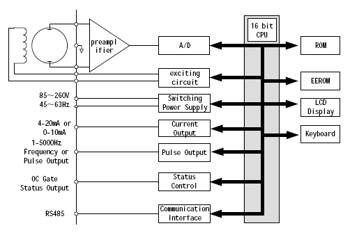
The converters supplies a stable exciting current to the coil in the sensor of electronetic flowmeters to get B constant and amplifies the electromotive force and convert it into standard signals of current or frequency so that the signals can be used for displaying, controlling and processing. The schematic of converter circuit is shown in Fig. 2.1.
Fig. 1 Schematic of converter circuit
2. PRODUCT CLASSIFICATION
3.1Product components
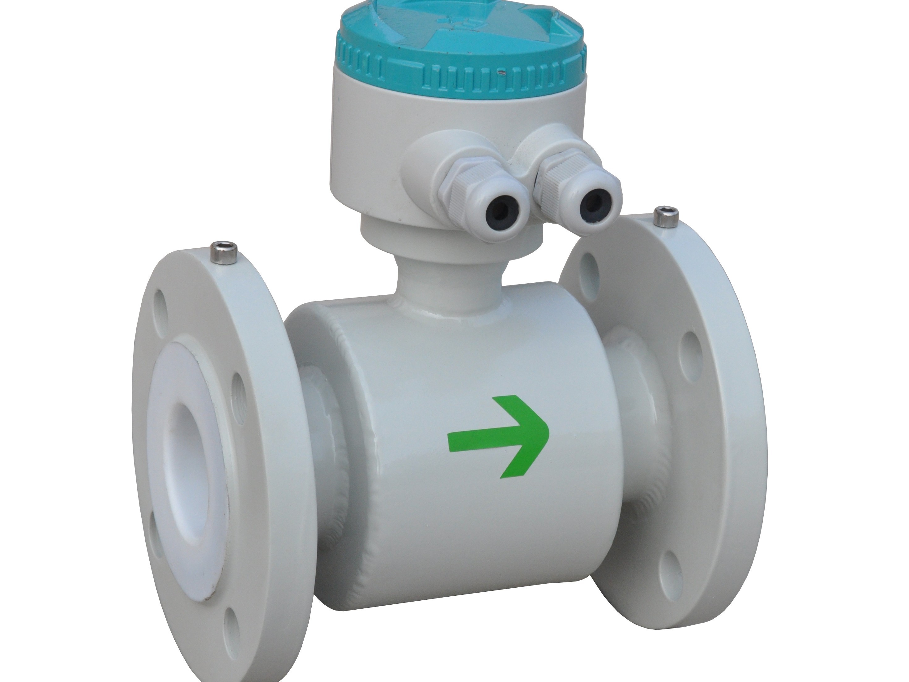
Electromagnetic flowmeter is composed of sensor and converter. The remote-type also needs a special double-layer shielded cable to connect the converter and the sensor.
3.2Product models
electromagnetic flowmeter has two forms: compact-type and remote-type. There are seven kinds of electrode materials and four kinds of lining materials available for sensor.
3. TECHNICAL SPECIFICATION
4.1The flowmeter is compliant to Standard “JB/T 9248-1999 Electromagnetic Flow Meter”.
4.2Maximum flow speed: 15m/s
4.3DN size: 3, 6, 10, 15, 20, 25, 32, 40, 50, 65, 80, 100, 150, 200, 250, 300, 350, 400, 450, 500, 600, 700, 800, 900, 1000, 1200, 1400, 1600, 1800, 2000
4.4Accuracy: 0.5%, 0.2%
4.5Nominal Pressure: 4.0MPa(DN0-150)
1.6MPa(DN200-600)
1.0MPa(DN700-1200)
0.6MPa(DN400-2000)
Or other specified by order
4.6Materials
Electrode Forms and Materials:
Electrode design has four forms: standard form, scraper form, detachable form and grounding electrode.
Electrode material is selectable from stainless steel containing Mo, stainless steel coated with carbonized tungsten, Hastelloy B, Hastelloy C, Titanium, Tantalum and platinum-iridium alloy.
Flange material: carbon steel
Grounding ring: stainless steel
Inlet protection ring: carbon steel, stainless steel
4.7Enclosure
IP65:
IP68: only available for remote-type sensor with neoprene or polyurethane liner, not including flameproof model.
4.8Flameproof Standard
DN15-DN600 compact-type: md II BT4
DN15-DN1600 remote-type: sensor and converter both installed in dangerous area: md II BT4.
DN15-DN1600 remote-type: sensor installed in dangerous area and converter installed in safe area: md II BT4
4.9Connection Cable
Special cable is needed to connect the sensor and the converter for remote-type flowmeter. The cable length should not exceed 100 meters. A 10-meter cable is supplied free of charge and the rest is to be ordered.
4.10General Specification of Converter
l Power supply: AC 85-265V, 45-63Hz, ≤20W; DC 11-40V
l Converter display and operation: four keys are available to set all parameters. External handheld or PC can be used to do the configuration. High resolution LCD display with backlight, empty pipe detection and self-diagnostic function are equipped in the converter.
l Digital communication: RS485, RS232, MODBUS,REMOTE
l Output Signals:
- Current output: fully-isolated, 4-20mA/0-10mA
load resistance: 0-10mA: 0-1.5KΩ; 4-20mA: 0-750Ω.
- Frequency output: bidirectional flow output. Frequency output is proportional to the flow percentage of the full range. The converter provides fully isolated transistor open collector frequency output ranged from 1 to 5000 Hz. The external DC power supply should not exceed 35V and maximum collector current is 250mA.
- Pulse output: bidirectional flow output. The converter can output up to 5000cp/s pulse series, which is dedicated to external totalization. Pulse factor is defined as volume or mass per pulse. It can be set to 0.001L/p, 0.01L/p, 0.1L/p, 1L/p, 2L/p, 5L/p, 10L/p, 100L/p, 1m3/p, 10 m3/p, 100 m3/p or 1000 m3/p. Pulse width is selectable from auto, 10ms, 20ms, 50ms, 100ms, 150ms, 200ms, 250ms, 300ms, 350ms and 400ms. Photo-coupler isolated transistor open collector circuit is used for pulse output. The external DC power supply should not exceed 35V and maximum collector current is 250mA.
- Flow direction indication: The converter is capable of measuring both forward and reverse flow and recognizing its direction. The converter outputs 0V low level for forward flow, while +12V high level for reverse flow.
- Alarm output: Two channels of photo-coupler isolated open collector circuit are used for alarm signal output. There are two alarm outputs: high limit alarm and low limit alarm. The external DC power supply should not exceed 35V and maximum collector current is 250mA.
- Damping constant: Damping time is selectable from 0.2 to 100s.
详细的电磁流量计英文说明书请点击下载。电磁流量计英文版说明书.doc
本文由于"苏州贝特智能仪表原创”https://www.beitemeter.com/articles/dclljj.html


咨询热线
400-839-1983